December 20, 2021
There are many industrial applications where mixing is needed to achieve either reaction or diffusion. Examples we see on the citrus side are reacting orange peel with hydrated lime to make cattle feed and washing sugars from lemon peel to make pectin peel. Recently the same equipment has been used to diffuse CBD oils into ethanol and to diffuse flavors from coconut meat into warm water.
We do this with horizontal screw conveyors which mix and convey the material en route to our screw presses. These conveyors may be paddle conveyors, ribbon flight conveyors, or conveyors with cut & folded flights.
Diffusion or reaction requires a fixed amount of time. Frequently this is tied to the temperature of the material. For example, a rule of thumb for citrus reaction conveyors is that the reaction time doubles for each 10ºC drop in temperature.
Once we know the residence time required in the conveyor, we use a spreadsheet to calculate the dimensions of the needed screw conveyor. The two givens we work with are the quantity of material to be processed per hour, and the ratio of liquid which is added to it.
For a coconut diffusion proposal, I was given 4,000 kilos per hour of shredded coconut meat, and I had visited a customer who added water in the ratio of 1.3:1. I guessed that diffusion would occur in about two minutes.
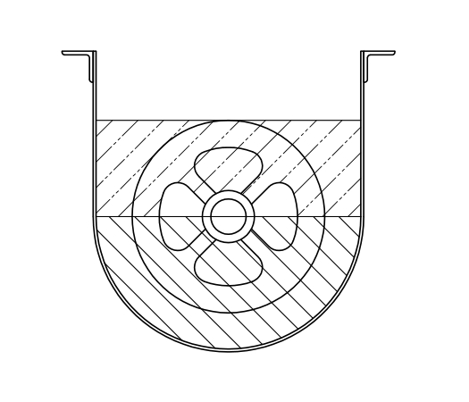
The spreadsheet assumes that the conveyor will be filled to the very top of the flight of the screw (or paddle or ribbon). The cross section of that mass would be a semi-circle from the center of the shaft to bottom of the trough, plus a rectangle from the center of the shaft to the top of the flights. We do not subtract volume to allow for space take up by the shaft and flights of the conveyor. The sketch below illustrates this.
For economy, we use standard trough lengths (“sticks” in the lingo of the screw conveyor industry). That is 9’8″ OAL for 6″, 9″, and 10″ conveyors, and 11’9″ OAL for 12″ through 24″ conveyors. We allow for the clearance between the flights and the trough. We also subtract, depending on the size we are working with, a foot or two of length for the inlet, and a similar amount for the conveyor discharge.
To select the conveyor, we use trial and error to pick the number of sticks and screw diameters. This is massaged until we come out close to the minutes of dwell time which are required.
Note that screw rpm does not enter into the calculations. That, with drive horsepower, comes later on.
We will be glad to email the spreadsheet to anyone who might have a use for it.
ISSUE #339