OVERVIEW
The Vincent KP Press consists of a screw rotating within a screen housing, a flanged inlet hopper, and a discharge opening. At the discharge end, the mouth of the screen housing is closed by a pneumatically actuated cone which moves back and forth on the screw shaft in proportion to the internal pressure in the screen frame. This motion is opposed by the cone cylinder thrust, thereby regulating the discharge of solids. An air regulator is provided to adjust the pressure on the cone. The liquids, which are squeezed from the wet product, escape through the screen housing and are caught in a built-in pan under the screen.
The screw is driven by a fixed speed electric motor that is C-face mounted to a gearbox. The gearbox reduces the RPM from the typical 1750 RPM output of the motor to an appropriate speed for the application, 5 – 50 RPM. The hollow bore gearbox mounts directly on the screw shaft and is flange mounted to the machine.
The numbers in the model designation stand for the nominal diameter of the screw in inches.
As the press has been adapted to many different applications, options have been added to the press. These include interrupted or continuous flighted screws, conical screws where the shaft increases in diameter, different shape inlet hoppers, different style cones, etc. As a result, not all the information contained in this manual will apply to your press.
SAFETY
A screw press, like any screw conveyor, is totally unforgiving. If clothing or a limb gets caught in a rotating screw, the screw will not stop.
• Wear safety glasses around the press.
• Avoid loose-fitting jewelry or clothing, including high-visibility safety vests. If vests are required, the Velcro, tear-away type are recommended.
• Always lock out electric and compressed air before working on the press.
• Dewatering presses squirt liquid out, particularly if screen covers are removed. If material is hot, acidic, or caustic, do not remove screen covers while operating.
• Wear gloves when performing maintenance.
• When removing the tailstock and discharge mechanism, watch for pinch points and hinged assemblies. Be careful when removing or installing the screw and screen when they are fed through the C-plate as this is a particular pinch point.
• Never stand near a press being suspended during installation.
• Provide an E-stop button near the press.
Keep hands out of the press inlet and press cake discharge area.
RIGGING
Be sure to properly support the press when lifting it from the truck. Usually a sling positioned under the inlet hopper, on the side closest to the gearbox, finds the center of gravity. On bigger presses, do not lift just one corner of the press, as it is possible for the frame to deflect, shifting the screw within the press.
INSTALLATION
These presses are typically called horizontal screw presses. This doesn’t mean that the presses must be installed exactly level from inlet to discharge. Presses are often installed at an upward angle. Consult the factory if you need to install the press at an angle above 15° as an adjustment to the gearbox may be required.
Be careful not to rack the press when tightening the mounting bolts. In the case of large presses, do not just bolt or weld the press down to a level foundation! Instead, first place the press where it is to be installed. Next, place shims between the press frame and the steelwork (or floor, concrete pedestal or foundation) to fill any gap where the press is to be anchored. Only after shimming (or grouting) should the press be pulled down tight. Doing otherwise can rack the frame of the press, and this can cause screw-to-screen interference.
A large press must be mounted solidly, preferably to a foundation or structural steel. If a press draws its full rated horsepower without the press being anchored to the floor, the frame of the press can twist.
For maintenance, the screw is removed through the cake discharge end of the press. Allow the space required.
To suit individual conditions, a hollow bore gearbox can be rotated 180o, 90o either way. Consult the gearbox manual or Vincent factory in these situations as it is likely that the oil level in the gearbox will have to be adjusted.
Material can be fed into the press many ways. You may need to allow for return feed of overflow material if more is fed to the press than it can take. When material is piped to a press in a closed piping system, it is important to have a 2″ vent line open to the atmosphere, along with an overflow return line. The vent is necessary to prevent a siphon effect which can induce a vacuum in the inlet hopper and reduce press capacity. The return line should empty above the surface of the return pit. The overflow should fill less than half of the cross section of the return line.
Spill containment is a consideration which should be considered, because it may be possible for un-pressed material to purge from the cake discharge of a press.
We recommend that a manual disconnect, for killing power to the motor, be installed close to the press.
A variable frequency drive (VFD) programmed for either variable speed or auto-reversing may be required, depending on the application. If not, the use of a reversing starter switch is recommended; they cost only a little extra. Such a switch is handy for clearing a jammed press.
It is possible that, when operating intermittently with very wet material left in the press between runs, the liquid may loosen the cake plug at the discharge. This might cause the plug to blow out upon start-up. To minimize this condition, the press can be installed with the discharge tilted upwards.
PRESS COMPONENTS
A/B/C/D-PLATES
There are four vertical plates making up the frame of the press, called out in the Nomenclature drawing at the end of this manual. The motor is connected to the gearbox with a stub shaft protruding toward the press. The stub shaft is connected to the screw with a coupling. Going into the inlet hopper is the inlet hopper seal assembly attached to the A-plate. This A-plate forms one wall of the inlet hopper.
The next plate is the B-plate. It forms the downstream wall of the inlet hopper. The screen starts at the B-plate. There may be a notch (or pair of notches), called a Cord Cutter, in the B-plate. Also, there may be a bar called Brian’s Stripper welded to the B-plate, inside the inlet hopper; it is designed to kiss the edge of the screw flight as it passes. These two features prevent long fiber pieces from balling up at the exit of the inlet hopper. See the “Cord Cutter and Stripper Pins” section ahead.
The next plate, the C-plate, supports the discharge end of the screen. The discharge cone touches the C-plate when the cone is in the closed position.
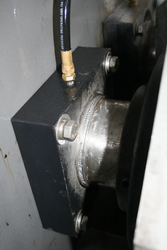
The final plate, the D-plate, has the twin air cylinders mounted on it. The screw shaft terminates at the D-plate via the attached flange bearing.
AIR REGULATOR AND CONE POSITIONING VALVE
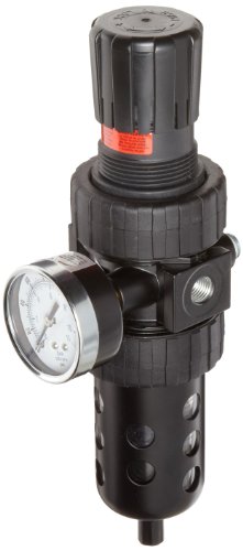
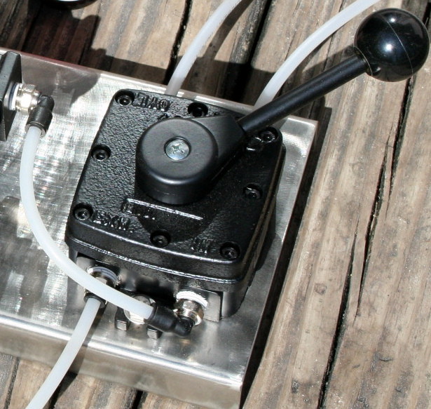
To regulate the air pressure of the discharge air cylinder, presses are supplied with an air pressure regulator along with a Parker 4-way cone positioning valve. These are typically installed near the cone end of the press. [Until recently FRL (Filter, Regulator, Lubricator) sets were provided to regulate air pressure. Most air cylinder manufacturers now recommend against the use of lubricators.]
The Parker valve allows manual selection of the shut, open, or “neutral” position. This valve connects air supply from the regulator to one end of the air cylinder, while simultaneously opening the other end to atmosphere. The vent line on the 4-way valve allows air to escape when pressure is switched from one end of the air cylinder to the other.
Continuous air flow from the Parker vent line indicates a leak inside the air cylinder, or possibly a faulty 4-way valve.
The neutral position of the Parker valve is used only in testing. If left in the neutral position, the cone will not move unless it is pushed open by press cake. If, later, the flow of press cake is diminished, the cone will remain in the position to which it was pushed, and purging can occur.
DISCHARGE CONE
The principal adjustment of the press is made with the discharge cone. The cone is the component at the cake discharge end of the press that acts as a door or stopper plug to restrict material from leaving the press. The more pressure exerted by the discharge cone, the drier the cake material will be leaving the press. Also, the motor amps can be expected to increase with added pressure, and throughput may decrease.
The discharge cone is moved in (actuated) either by an air cylinder or, rarely, by weights. Typical air cylinder pressures are in the range of 30 to 60 psi. Some materials will press only in a low range, say 10 to 20 psi. Other materials may press best with a pressure of 60 to 100 psi. Air consumption is minimal in all models, 1 to 2 cfm.
During initial, first-time start up, presses with air cylinder actuators are generally started up with the discharge cone in the withdrawn position. This will avoid an unnecessary jam. With the air cylinder models, the discharge cone mechanism can readily be positioned in the “open” (withdrawn or “out”) position.
Note that with many materials it is necessary to start the press with the discharge cone in the closed position at low air pressure. Thin or soupy materials, like pumped manure or clarifier underflow, can tend to purge right through the press if the press is operated with the discharge cone open [in the withdrawn (“out”) position]. However, with materials that are dry to begin with, such as sawdust or plastic wash tank sludge, it becomes more important to start with the discharge cone in the open position. This is because these materials may tend to jam or overload the press. Similarly, high freeness materials, from which the water falls away freely, will tend to jam in a press. Start the press with the cone open, then close it with low air pressure initially, when running such materials for the first time.
Most presses are operated 24/7. Once you are through the initial startup, it will be unlikely that your press should have the cone opened before starting. Most operators rarely open or shut the cone once it is set. However, it is recommended to cycle the cone in and out once per shift. This ensures that grease for the bushings is spread across the screw shaft.
As the pressure on the discharge cone is increased, not only will the cake become drier, but the flow through the press may also be reduced. With very slippery or slimy feed material it may be possible to apply enough discharge cone pressure to stop the flow altogether.
High discharge cone pressures can result in increased quantities of suspended solids in the press liquor.
Care must be taken if a press is to be left running at a very low pressure like 10 psi. If some fiber enters between the cone bushing and the screw shaft, it will take more than that much pressure to close a cone which has been pushed open by a heavy flow of cake. The result will be either high moisture content in the cake or, worse, purging.
With some feed materials, the press can be operated with the discharge cone in the withdrawn position. The screw alone may do enough compressing and dewatering to produce a cake at the discharge.
It is acceptable to open the discharge cone, in most cases, during normal operating conditions. This allows inspection, while in operation, of the discharge end of the screw and screen. This will give the operator a chance to observe operation with minimum dewatering and maximum throughput. It is also a good technique for purging bad material, i.e. either jammed or spoiled material, from the press. (Do not try this trick if you are pressing hot or chemically aggressive materials.)
Where very low air pressure is required for proper operation, it may be practical to put the cone positioning valve in a neutral position, halfway between open and closed. A press cannot be left permanently in this condition: keep in mind that a slug of cake will push the cone open, and it will not re-close on its own afterwards.
An unusual technique is to set the air pressure so that the cone normally stays completely shut. A timer is used to periodically open the cone. The closed period is determined by the amount of time required for press cake to accumulate in the press. This type of operation is used with slippery or slimy press cake that cannot be dewatered to sufficient firmness to force the cone open. The duration of the “cone open” period is long enough to dump much of the press cake that has been formed. Vincent Cone Timer panels are available at a minimal cost.
Once through start-up, the cone is almost always left in the closed position at whatever air pressure has been found to be effective. A plug of cake will be left around the cone whenever the press is turned off; this will normally clear on its own accord on restarting the press. To prevent a potential jam upon restarting, it is a good idea to open the cone for a few minutes prior to shutting down the press, after flow to the press has been stopped. Although there will be solids left in the press, they won’t be highly compacted.
There are a few applications where the air cylinder is removed and replaced with a jacking bolt. This is used if the cone pushes completely closed even with the lowest air pressure. It results in operating the press with a fixed discharge annulus, or air cylinders with linear actuators are available.
CONE BUSHINGS
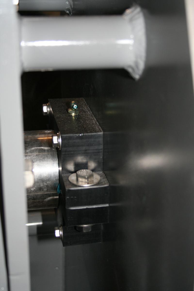
The cone rides on the shaft of the screw. “Cone Sleeve” is the name given to the portion of the screw on which the cone rides. There are dual bronze or UHMW bushings in the cone to support and guide it, and to protect the Cone Sleeve journal surface of the screw shaft. Sometimes the bushings are lubricated with liquid from the material being pressed, such as the juice from apples or water from pectin peel. Sometimes there is a grease fitting provided for lubricating the bushings or to minimize leakage of press liquor through the cone bushings. And sometimes, an AutoLube is included for automated lubrication of the cone bushing.
Bushing lubrication is extremely important when materials that are dry (like paper mill screen rejects) are being pressed. By the time such materials reach the discharge of the press, they do not have enough free moisture left in them to adequately lubricate the cone bushings. In these applications the operator should, at the start of each shift, pump grease in until it comes out between the cone bushing and the screw shaft. Then he should open and shut the cone three times in order to spread the grease.
Rarely, presses are supplied with additional lubrication fittings so that water, in addition to grease, can be metered to the bushings as a lubricant.
Automatic grease systems are available but only usable for fixed (non-rotating) cones. These should be the high pressure (900 psi) electric or battery variety. Vincent provides these for critical applications, especially pulp & paper.
Liquid leaking past the cone bushings drains out the back of the cone (at the air cylinder end of the press). Almost always it is minimal compared to the flow of press cake. However, a pan can be provided to collect this liquid and drain it into the main flow of press liquor.
SCREW / SCREW CONFIGURATIONS
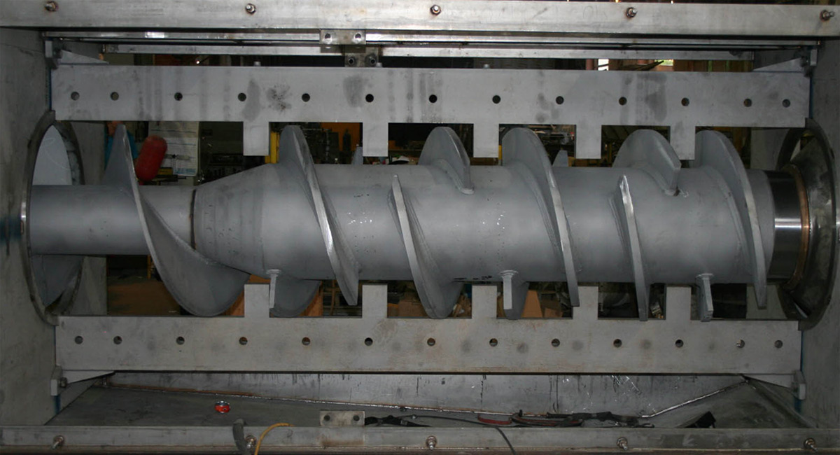
Most Vincent screw presses use the Interrupted Flight Screw design. The interruptions leave room for stationary resistor teeth that are mounted outside of the screen. These teeth go through the screen and reach almost to the shaft of the screw. This design of screw press stands in contrast to a Continuous Screw design. The main advantage of the interrupted design is that solids material must accumulate in the interruptions until sufficient consistency is reached for the solids to be pushed toward the cake discharge. There is a reduced tendency for the material being pressed to co-rotate with the screw. Also, there is more agitation within the press and, consequently, quicker and more thorough dewatering. Pushing the material through the compression zones past the teeth will also shred the material a bit.
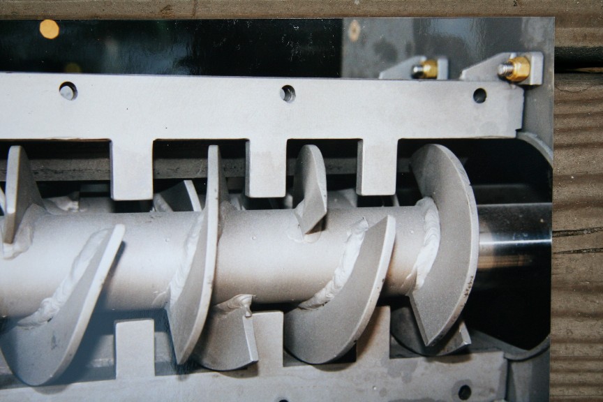
For applications where tramp material is more likely to enter the press, a continuous-flighted screw is often used. Typically, if maximizing dryness is a priority, the screw shaft is tapered to provide increased compression.
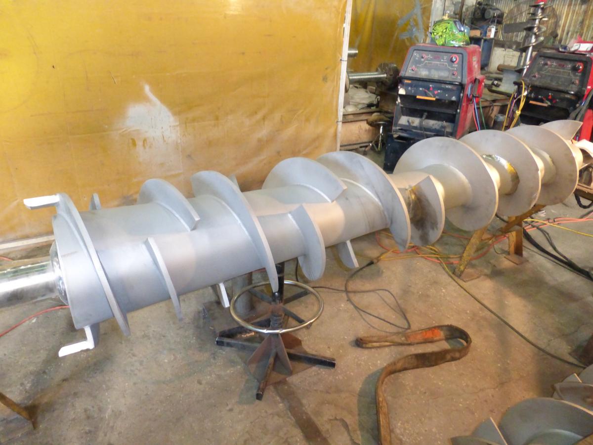
All screws start with a feeder section of continuous flights. This picks up material in the inlet hopper and pushes it into the screen section. The feeder section ends at the first resistor tooth. This feeder section of the screw is followed by compression stages where the flights have reduced pitch. The reduction in pitch of the flights results in compression of the material going through the press.
A screw configuration referred to as Sterile Butterfly is occasionally used. Sterile is a reference to a company, not cleanliness. There are a reduced number of flights on this screw, and the flights do not wrap as far around the shaft as is normal. This screw design is good for high throughput of materials which are easily dewatered and might jam the press.
WING FEEDERS
Sometimes there are blades welded to the outside tips of the last two flights of the screw. Called “Wing Feeders”, these are mounted parallel to the discharge screen surface. Care must be taken that wing feeders are not made so long that they hit the face of the cone when the cone is in the closed position.
Wing feeders can serve two purposes: (1) In the case of materials that want to channel out the discharge of the press, like pineapple and spent brewer’s grains, long wing feeders break
up the channeling flow and (2) For abrasive applications, short knobby wing feeders are provided as sacrificial wear elements.
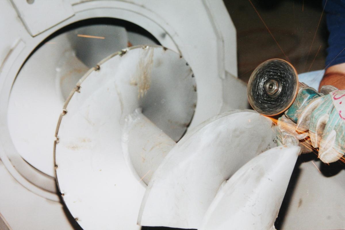
When certain materials are fed through a screw press, clumps of dry material may accumulate between the wing feeders and the screen. This buildup can cause wear of the screen. Should the problem occur, grind off the wing feeders.
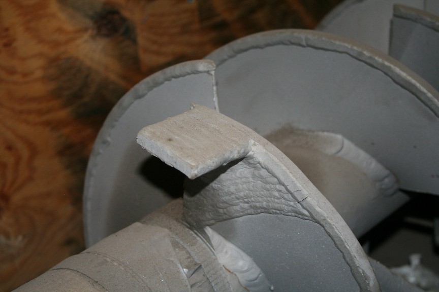
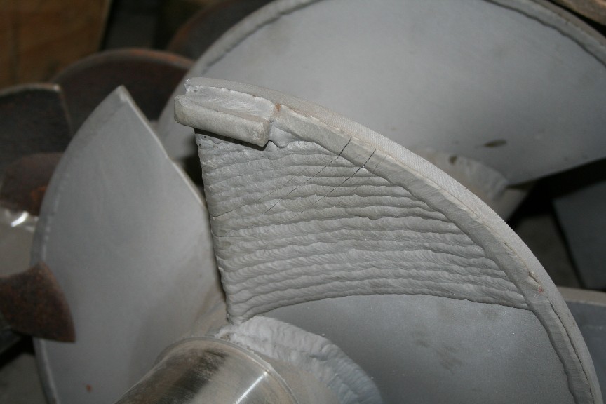 Knobby Wing Feeder
NOTCHES
Sometimes it is necessary, during press operation, to have the screw wipe the screens clear of blinding material. This is best achieved by having notches in the outer edge of the screw. Fibrous material accumulates in the notches and brushes away slimy material which may be blinding the screens. Shallow notches (1/8″ wide by 1/8″ deep, 1-1/2″ apart) in the outer edge of the screw flights work well. Typically, notching is done from the B plate to the second resistor tooth. Most Vincent presses are supplied with notches.
RESISTOR TEETH
The interrupted screw design press has stationary teeth that protrude into the flow of material as it passes through the press. These fit into the gaps of the screw where there is no flighting. They stop just short of the shaft of the screw. These resistor bars are on top and bottom of the screens and the screens bolt up to them.
Rarely, the resistor teeth are shortened, usually by half, to increase the capacity of the press. Removing the teeth altogether will result in co-rotation and jamming.
Occasionally, the resistor teeth are drilled so that fluid can be injected into the press during operation.
INVERTER VFD & PLC CONTROL
It is always recommended that an inverter VFD be used to start, protect, and operate the screw press. With a VFD it is possible to establish the optimal combination of screw speed and discharge cone air pressure. The VFD also can be used to reverse the press in case of a jam or to slow it down during upset conditions.
Nine presses out of ten will operate unattended, indefinitely, and just fine at line frequency of 50 or 60 Hertz. If two screw presses are mounted in parallel, they are usually fed with a screw conveyor which drops to fill the first press, with the rest going to the second press; this is followed with a drop-out for overflow.
However, we need to address the exceptions:
Use of level controls is becoming more and more common. These are used to regulate either the flow going into the press or to regulate the screw speed.
In some applications a press is sized for handling upset conditions of large flow, while the normal flow is quite small. In these cases a level control is used, and the PLC can be programmed to turn off the press when a low level is reached in the inlet hopper, and the press re-started when a higher level is signaled.
In some cases the press will tend to jam, overload, and trip out on high amps. In this situation it may be necessary to program the controls so that the cone automatically goes open on high amps, re-closing at a lower set point. This arrangement requires a solenoid operated 4-way air valve, replacing the manual valve which is provided with the press.
In other cases of jamming, a simpler arrangement is to install a Cone Timer. A timer is used to periodically open the cone. The closed period is determined by the amount of time required for press cake to accumulate in the press. The duration of the “cone open” period is long enough to dump most of the press cake that has formed. This type of operation may be used if the press periodically experiences jamming or overload due to fluctuations in the amount of material being fed into the press. Alternatively, it may be used with slippery or slimy press cake that cannot be dewatered to sufficient firmness to force the cone open. Cone Timer panels are available from Vincent at no charge.
Some applications require the use of a specially programmed variable frequency drive. In this case the VFD is not used to change the speed of the press, but, rather to set it for auto-reversing operation. By having the screw run backwards for three or four turns every few minutes, some difficult-to-dewater materials can be pressed much more effectively. This operation can help a great deal with material which tends to blind (cover over) the openings in the screen. Vincent has loaner VFD’s if you want to give it a try. The technique works well on bar screens; care must be taken with perf screens so that the screw does not snag the screen during the reverse cycle.
Once through start-up, the cone is almost always permanently left in the closed position at whatever air pressure has been found to be effective. A plug of cake will be left around the cone whenever the press is turned off; this will clear on its own accord on restarting the press.
However, some materials may set up and become hard, or freeze, within the press when the press in turned off. This is especially true in the case of pressing wet coffee grounds or outdoor installations. For these applications it is advisable to open the cone for a period of one minute before turning off the press. This allows the press to partially empty itself, fluffing the material left in the press. Vincent can provide information for automating this procedure.
SCREENS
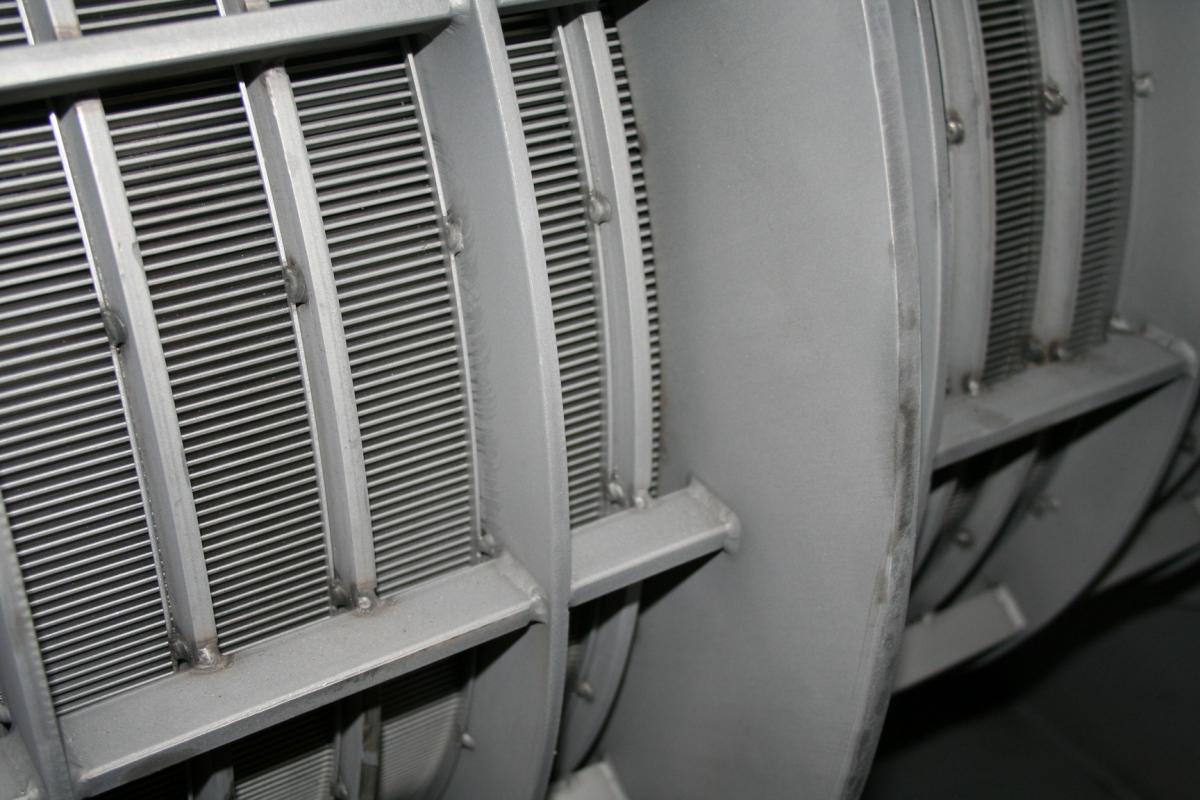
The screens of the press are made either of wedgewire or profile bar (slotted screen) or perforated stainless sheet (round holes).
Screens made of wedgewire come standard with 0.015″ to 0.020″ slot width; they are also available with slots that are 0.006″ to 0.060″ wide. With slot widths less than 0.012″ there is a tendency for the screen to blind (be covered over) with the material being pressed. However, they work well in alcohol and oil separation. Changing the slot width generally has little impact on the clarity of the press liquor or the dewatering capacity of the press. These screens are reversible as most wear will occur at the discharge end. This doubles the life of the screen. When worn, the entire wedgewire assembly must be replaced.
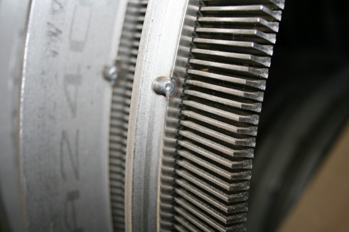
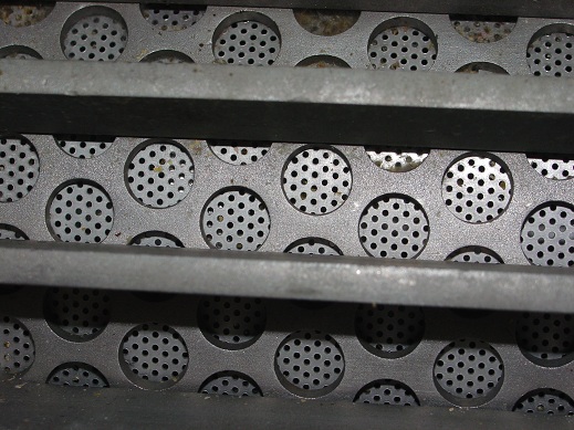
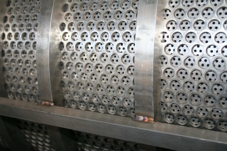
Perforated metal screens are usually a simple sleeve made from rolled perforated plate which is held in the screen assembly. These are less durable but usually only the inner screen, the screen insert, must be replaced, reducing cost.
The most common damage to a wedgewire screen is for part of the surface to be smeared over from being rubbed by the screw. This rarely is bad enough to affect press performance. Profile bar screens generally work satisfactorily with 30% or even more of their surface smeared over. Smeared screens can be remedied by running a box cutter blade through the slots. Small holes can just be patched with sheet metal to extend life. In cases of severe wear or damage, it is common to patch a screen. Stainless sheet metal is used for this. The reduction in drainage surface is of little consequence as the screens have ample open area.
Standard perforated screens have a hole size of 0.094″ diameter, although material with 0.050″, 0.033″, down to 0.023″ holes can be supplied. Surprisingly, usually there is little difference in the degree of filtration achieved by either changing hole size or going to a slotted profile bar screen.
Frequently, increased press capacity can be achieved by changing a perforated screen to one with smaller holes. This unexpected result arises from a combination of factors: (1) smaller hole screens are made of thinner sheet metal, so the press liquor has a shorter distance to travel before it falls free from the screen, reducing the chance of blinding and (2) particles which fall into and plug a larger hole will roll over a smaller hole. Minor rubbing between the screw and screen is normal, although, obviously, hard rubbing will cause wear and premature failure of the screen. With a clearance greater than 3/16″, the dewatering performance of the press can start to deteriorate; this depends a lot on the nature of the material being dewatered.
The most common cause of screen failure ties to failure of the outboard support bushing. If the bushing holding the end of the screw wears out, it can let the screw move enough to rub against the screen.
Profile Bar / Wedgewire Screens
Perforated Screen Assemblies
CORD CUTTER AND STRIPPER PINS
Sometimes long stringy material will be pinched where the feeder portion of the screw goes through the hole in the B-plate. This material will co-rotate with the screw and build into a bundle which reduces flow through the press.
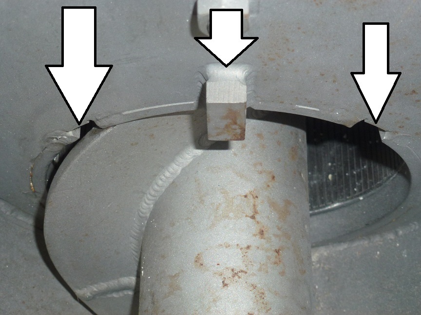
A groove, like a 3/8″ deep keyway, is cut halfway through the hole in the B-plate. We call this a Cord Cutter. Material trapped between the flight and the hole in the B-plate will pop up slightly as it passes the Cord Cutter. The result is that the material is sheared loose.
A part called Brian’s Stripper may be welded to the B-plate, inside the inlet hopper. It goes in a position so that the flight lightly kisses the stripper as it goes past. This strips the material away. Strippers are made of square bar.
MOTOR / GEARBOX
Vincent presses are almost always supplied complete with a motor. Standard motors are 60Hz, Inverter Duty, TEFC, 230/460V. We will supply whatever motor is called for where the press is headed, 575V, 50Hz, whatever. Motors used are standard, off the shelf motors, easily replaced if needed from your local motor distributor.
Specialty motors are available upon request, including stainless, washdown duty, explosion-proof, etc.
Standard gearboxes supplied are NORD parallel shaft. Gearboxes are supplied with the oil at the right level for horizontal mounting. If the press is mounted off horizontal, a change could be required in oil level. Sometimes, to increase capacity, the press is sped up to 120 Hz or a 3600 RPM motor is installed. If your press is going to be run at high speeds, NORD recommends changing the oil to synthetic.
Both a motor manual and a gearbox manual are supplied toward the end of this manual.
SHAFT SEAL
Consult the Parts List contained in this manual to determine what type of seal plate assembly you have. The Seal Plate is bolted to the A-plate. This housing may be solid UHMW (ultra-high molecular weight polypropylene or polyethylene) and it may contain one or two Johns Manville (JM Clipper) lip shaft seals. There may be a grease fitting on this plate; the grease is used to reduce leakage and to help prevent fibrous material from entering and damaging the screw shaft.
Generally, seals are allowed to drip once they start leaking. They are replaced only in conjunction with major maintenance, as when the screw is removed from the press.
In some cases, we have found that leakage from a shaft seal can be stopped by simply selectively loosening or tightening the four bolts holding the seal housing to the A-plate.