Home »
INSTALLATION
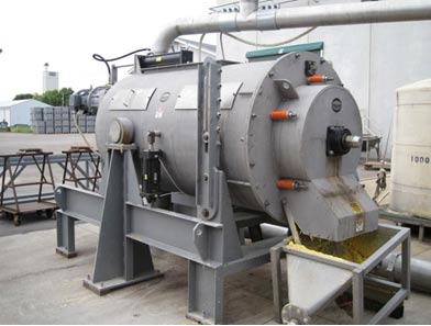
The Fiber Filter may tend to vibrate, so for a permanent installation you will want to anchor all the feet of the machine to supporting structure.
Note that, since the angle of inclination to be adjusted, flexible hoses must be used for the inlet flow and, possibly, the filtrate flow. Be sure to allow enough hose length for full travel of the tilting mechanism without interferences.
Changing the filter sleeve assembly is required periodically. To accomplish this, convenient floor space must be left at the sludge discharge end of the machine.
Operating the optional sleeve flushing mechanism requires space at the drive end of the Fiber Filter so that the flush liquid supply hose and tube can move in and out.
The filtrate flow can be allowed to empty into a tank or collection pan mounted under the machine. (Such a pan is useful to the operator for detecting a torn filter sleeve.)
It is important that provision be made to immediately shut off the flow of liquid going into the Fiber Filter in the event that the drive motor is stopped or trips out. The inbound flow going into the Fiber Filter will purge through the sludge discharge chute if the rotor stops turning. Provision should be made for this eventuality.
It is best to make provision to by-pass both part and all of the inbound flow to the Fiber Filter.
Spill containment is a consideration.
RIGGING
The Fiber Filter may have a lifting eye that is positioned at the top of the machine, near the center of gravity; a chain can be slung through this hole for lifting. Alternatively the machine can be lifted from below with a forklift.
START-UP
Before putting power to the Fiber Filter, the rotor should be turned by hand to make sure that it turns freely. This can be done by taking the cover off the end of the motor and turning the cooling fan by hand. Also, it can be done by reaching through the sludge discharge chute to grip and turn the rotor. Be sure the motor starter is locked out when performing this procedure.
The rotor of the Fiber Filter turns in a counter-clockwise direction, when viewed from the drive end of the machine.
Be sure that the spring tension is set correctly tight prior to start up.
INSTRUMENTATION
In almost all cases satisfactory operating conditions can be achieved by adjusting the elevation of the Fiber Filter. However in some cases, driving the Fiber Filter with a Variable Frequency Drive can be useful in optimizing performance. The use of a VFD can be valuable during initial start-up for establishing the best pulley ratio for future fixed speed operation (if a belt drive is used).
A useful instrument for testing a Fiber Filter is an ammeter. This is particularly true if there are high concentrations of solids in the flow to the Fiber Filter.
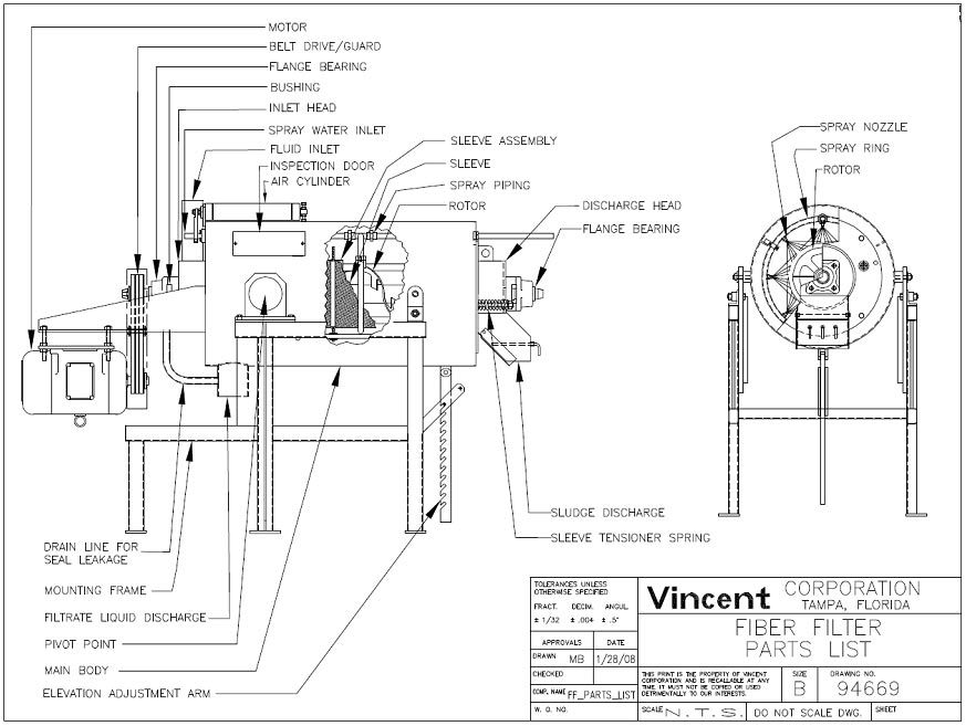
SPRING TENSION
The Vincent Fiber Filter features an External Fabric Tensioner. These springs can be adjusted with the machine in operation. Usually spring tension is adjusted only once after initial stretch has occurred in a new sleeve.
The effect of spring adjustment on capacity and filtration is minimal. However, tight spring adjustment is vital for achieving long sleeve life. The fabric must be kept taught; otherwise it will flutter and fail in a few days.
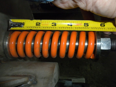
On the Models FF-12 and FF-30, the springs have a free length of 6″. These should be compressed 1″, to 5″ length, for proper tension on the fabric sleeves. In the case of the FF-6, the springs are 4″ long and they should be compressed to 2-1/2″ length. (Some FF-6 machines have 6″ orange springs; these should be compressed to 5-1/2″.)
 |
 |
| FF-6 TIGHTENED TO 5-1/2″ | FF-12/30 TIGHTENED TO 5″ |
The springs will normally stretch out by 3/8″ to 3/4″ during initial operation of the Fiber Filter. The spring compression should be re-set after this occurs.
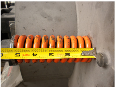
OPERATION
The Fiber Filter separates a flow containing dilute solids into a stream of filtrate and sludge. This sludge will be quite wet; however, it will contain the majority of the insoluble (fiber) solids. The Fiber Filter is not a press, so it does not separate the solids into a cake. When starting with a clean, empty Fiber Filter, it can take several minutes for the first sludge to appear at the discharge. This is because the fabric sleeves can hold up to five minutes worth of sludge.
With a very dilute feed, one would expect around 95% of the flow fed to the Fiber Filter to come out as filtrate and 5% as sludge. This can vary significantly in applications where there is high solids consistency in the feed to the Fiber Filter.
If excessive vibration or high motor amps are evident, it is likely that the solids are not discharging from the sleeve. This can be remedied by either (a) lowering the elevation angle of the machine or (b) increasing the flow of liquid into the machine. (It can also be an indication that sludge has bridged and is accumulating in the sludge discharge spout.)
In some applications the operation of the Fiber Filter is cyclical. The operating cycle can range from a few seconds up to two minutes. The cycle starts with a longer period of minor vibration and minimum solids (sludge) discharge. This is followed by a shorter period of stronger vibration and a heavy discharge of sludge. This occurs with a constant, uniform inbound flow and a steady discharge of filtered liquid.
It must be anticipated that the Fiber Filter may purge. Under this condition the inbound flow will discharge, unfiltered, through the sludge discharge chute. This condition will occur if the electrical power to the Fiber Filter is interrupted without the inbound flow being shut off. It can also occur if the sleeve becomes blinded (coated over); if the elevation angle is too low; or if inbound flow conditions change.
The Fiber Filter will overload and trip out if excessive solids accumulate within the sleeves. This occurs if there is insufficient liquid flow through the machine. The condition can be avoided by reducing the angle of inclination of the Fiber Filter. The overload condition will occur either if the machine is set to operate with a thick inbound flow and this flow is significantly reduced, or if the solids content of the inbound flow is significantly increased, without lowering the angle of inclination. Alternate rotor configurations are available that avoid this problem.
 |
 |
| STEEP INCLINATION | LOW LEVEL INCLINATION |
Excessive splashing of liquid from the sludge discharge chute is corrected by backflushing the sleeves, by increasing the angle of elevation, or by reducing the inbound flow (gpm).
The rotor of the Fiber Filter turns in a counter-clockwise direction, when viewed from the drive end of the machine.
However, it has been found that operation in the reverse direction, with certain rotor designs, may produce improved results. Reverse operation may be appropriate if excessive splashing of liquid from the sludge discharge chute occurs. Try this before you give up.
VARIABLES
The five variables, in order of importance, that affect Fiber Filter operation are:
- FEEDING: Volume of inbound flow;
- INCLINATION: Angle of inclination of the rotor;
- SLEEVES: Mesh of the fabric sleeves; and
- BACKFLUSH: Cleanliness of the fabric sleeves;
- RPM: Rotational speed of the rotor.
This assumes that solids consistency in the inbound flow is not a controllable variable.
FEEDING
Fiber Filters require that the feed to the machine be at a constant flow rate. The feed must be at low pressure. Good performance of the Fiber Filter can be achieved by gravity feeding from above. An overflow line can be used to maintain constant head and flow.
The Fiber Filter can also be fed by pumping a flow directly into the machine. A variable speed pump, especially a diaphragm pump, works best. A regulating type valve, such as a globe valve, may be required to adjust the inbound flow.
INCLINATION
The principal adjustment of the Fiber Filter is made by changing the angle of inclination. In general, with a steeper angle, greater dewatering is achieved. Usually greater throughput capacities can be achieved with a more gentle angle. The fluttering cycle and vibration intensity are also affected.
If the angle of inclination is too great, or if the inbound flow is too little, it is possible that no sludge will be produced. In this situation the suspended solids in the flow are being disintegrated and beaten through the sleeves by the action of the rotor. This condition is normally accompanied by mild to severe fluttering of the sleeves.
Not uncommonly, with certain rotor designs it will be necessary to aim the Fiber Filter downward, with the discharge below the horizontal. This occurs with either very thick flows or very low gpm flows. It occurs when there is not enough liquid present to flush the slurry/sludge from the Fiber Filter. (It may be necessary to place a block under the elevation pivots or the feet of the machine in order to achieve a downward angle.)
If the angle of inclination is too high for a given flow, or if the inbound flow is too low, the fabric sleeve will fill with solids. This can lead to severe fluttering of the fabric, and the Fiber Filter may trip out on electrical overload or the sleeves may fail.
FABRIC SLEEVES
The fabric sleeves of the Fiber Filter are made of tweed woven monofilament fabric. The synthetic polymer fabric is selected according to a rating of micron size. In addition, the fabric is selected for its rating in terms of tensile strength (circumferential as well as axial) and chemical and temperature resistance.
Standard polyester sleeves are good to 220o F and are resistant to both caustic and acid cleaning solutions. PEEK sleeves are good for 350o F.
Micron ratings of 20 to 190 are typical. These relate to the size of the particle that will pass through the sleeve, not to the passage size through the filaments of the fabric.
The following chart lists common sleeves:
| Micron Rating | Air Perm | Mesh | Nominal | Opening | Material |
| RLX | 572 | 80 | 0.007″ | 0.190 mm | Polyester |
| 155 | 260 | 100 | 0.006″ | 0.150 mm | PEEK |
| 132 | 299 | 110 | 0.005″ | 0.118 mm | Polyester |
| 118 | 501 | 120 | 0.005″ | 0.118 mm | Polyester |
| 86 | 234 | 170 | 0.0035″ | 0.086 mm | Polyester |
| 50 | 72 | 270 | 0.002″ | 0.050 mm | Polyester |
| 43 | 208 | 325 | 0.002″ | 0.045 mm | PEEK |
| 31 | 39 | 500 | 0.001″ | 0.030 mm | Polyester |
| 20 | 24 | 0.0008″ | 0.020 mm | Polyester | |
| 12 | 19 | 0.0005″ | 0.012 mm | PEEK |
PEEK sleeves are seven times stronger that polyester, but cost twice as much. This fabric is more chemical resistant, also.
The sleeves quiver while the Fiber Filter is in operation. This action keeps the sleeve from blinding. A quivering action is normal and will result in very long sleeve life. Fluttering, on the other hand, reduces sleeve life. It ultimately results in the failure of the fabric. Replacement is simple.
BACKFLUSH SYSTEM
In certain applications the fabric sleeve of the Fiber Filter may become blinded with usage. This may be corrected by using the backflush system. The frequency at which this is necessary varies considerably: it can be as often as twenty times an hour. Or, operation once a shift or once a day may be all that is required.
Some sanitary applications require that the machine be flushed for CIP purposes. This is done with the backflush system.
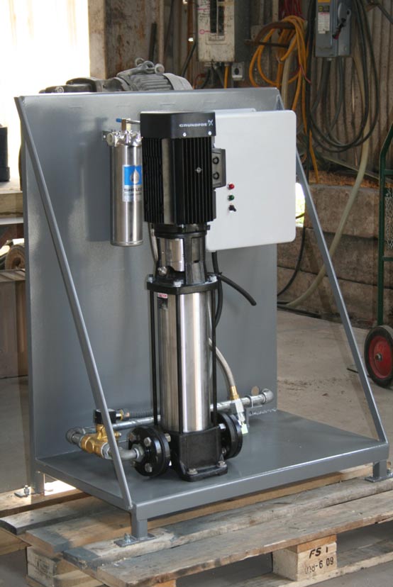
This backflush system consists of an internal spray rings with nozzles directed to spray the outside of the fabric sleeves. The spray ring is moved back and forth inside the Fiber Filter either by hand or by an air cylinder mounted on the outside. A booster pump is included to increase the pressure of the spray fluid. A canister filter is included to prevent plugging the spray nozzles. A control panel is included that allows setting the frequency and duration of the spray cycle.
The backflush system is designed to operate with 200 to 250 psi at the nozzles. It can be operated with or without the rotor in operation, and with or without flow through the machine. The preferable mode is with the machine in normal operation (full flow through the machine at normal rotor rpm).
Backflush fluid can be water or CIP solution. In some cases it is necessary to use chemical cleaners such as caustic or acid in addition to a water flush cycle.
RPM: FIBER FILTER SPEED
Optimal operation of the Fiber Filter is almost alwaus achieved by adjusting the elevation. With consistent material being fed to the machine, especially with an elevated tank for gravity feed, constant speed should be perfectly adequate. In a few cases superior performance may be achieved by driving the unit with a Variable Frequency Drive (VFD). In such case the Fiber Filter speed (rpm) can be set later by changing drive sheaves (if a belt drive is used).
In general, higher speed results in higher throughput capacity. It can also result in splashing of wet material from the discharge and reduced solids concentration in the sludge/slurry discharge. High speed operation increases the power draw of the motor.
In applications involving filtration of a variety of solutions, or inconsistent inbound flow, the Fiber Filter is best equipped with a VFD.
SLEEVE LIFE
The most common sleeve failure is a tearing at the hem. The second most common is a failure of the seam. These failures generally occur because the machine is allowed to operate with the fabric in a fluttering condition. When this occurs the machine will be seen to vibrate, and rattling noise will be heard from the spray rings inside the machine.
To prevent fluttering:
- Be sure the springs are quite tight (not loose).
- Lower the inclination so that wetter sludge is produced.
- Increase the flow into the machine so that solids do not accumulate inside.
- Switch to a heavier, preferably PEEK, fabric sleeve.
CAPACITY MEASUREMENT
The best way to measure capacity of a Fiber Filter is to collect timed samples of filtered liquid and discharge sludge. Allowing the filtered liquid to accumulate in a tank, and measuring the change in depth over time, works well. Similarly, a 5-gallon pail is suitable for collecting discharge sludge.
PERFORMANCE MEASUREMENT
For a quick performance measurement of the Fiber Filter it is convenient to collect samples of inbound and filtered liquid. These should be equal size samples (one fluid ounce is typical). These samples are poured into the center of a piece of cotton cloth; making a ball and twisting the cloth will force the liquid through the cloth. The fiber will remain on the cloth, allowing a visual comparison between inbound and outbound.
Similarly, samples of inbound and outbound liquid can be collected in Imhoff cones or jars and allowed to settle. The differences noted give an idea as to the effectiveness of the machine.
Use of a laboratory centrifuge on inbound and outbound samples permits a more quantitative measurement of performance. Similarly, oven drying of filter samples permits a quantitative analysis of suspended (insoluble) solids. If the fluid being filtered contains dissolved solids (sugars), the samples should be washed to zero Brix as part of the testing procedure.
SLEEVE CLEANING
In some sanitary applications it is necessary to remove the filter sleeve assembly from the Fiber Filter and soak it in a cleaning solution such as caustic. This may have the benefit of shrinking the fiber back to a taught condition, depending on the fabric material being used. Purchase of a spare sleeve assembly is recommended for this type of operation.
SHUT-DOWN
When shutting down the Fiber Filter, the sleeve assembly should be cleaned. If practical, this should be done by admitting fresh water to the inlet of the machine.
Also, the backflush system should be used. This is done by leaving the machine in operation (rotor spinning) but with no flow being admitted. It will help to lower the angle of inclination of the Fiber Filter. Operate the back flush system to clean the fabric sleeves. This will prevent solids either from overloading the machine on start-up or from crusting on the fabric.
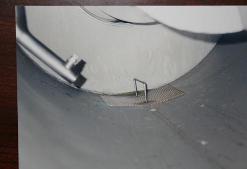
SLEEVE FAILURE DETECTION
A metal screen can be installed over the filtrate drain in the barrel of the Fiber Filter. Should a sleeve fail, fiber will blank over this screen and cause liquid to drain from the discharge head, alerting an operator. This type of screen is illustrated below.
 |
 |
 |
LUBRICATION
There are up to four grease lubrication fittings on the Fiber Filter. These are on the shaft seal housing and flanged bearing at the inlet as well as the shaft seal housing and flanged bearing in the discharge head. Normal bearing grease is suitable for the shaft seals.
FABRIC SLEEVE REPLACEMENT
The most important item in changing a fabric sleeve is to note that the seam is either a lap or double hook joint. Arrows are printed on the sleeves to denote the direction in which the rotor should go past (sweep over) the joint (seam).
The arrows assure that the seam is installed so that the waves of liquid sweep over the blunt edge of the seam, not against it. That is, sleeves should be installed so that the blunt edge of the lap joint is not facing into the waves of liquid that are pulsed by the rotor. While it is harder to visualize, the same effect is true with the double hook seams.
If the sleeve is installed the other way around, the wave of liquid created by the moving rotor paddle will hit an edge of fabric. This leads to early seam failure. This is true although there may be a film adhesive, which laps over the joint of fabric in a smooth manner.
It is important to take a few extra minutes when changing a sleeve. The seam should be straight with the main axis of the machine; the two hems should be uniform, without any pinches; there should be no dips or ripples in the fabric surface.
To properly install a new sleeve, first position it reasonably uniformly and clamp it tight. Next, slightly tension the sleeve temporarily with the tensioning springs. This will make evident any non-uniformly tensioned areas. Loosen the sleeve clamp at one end and tap it so as to pull the fabric tight; then re-tighten the sleeve clamp.
The location of the seam of each sleeve should be noted. Most commonly the seam is placed where it can be seen through the inspection door.
Safety tip: when inspecting sleeves with the machine in operation care must be taken. There is a natural tendency to poke a finger through a suspected hole. If this is done with the machine in operation, the rotor will surely sever the finger.
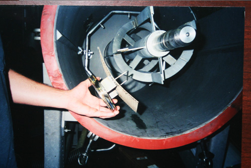
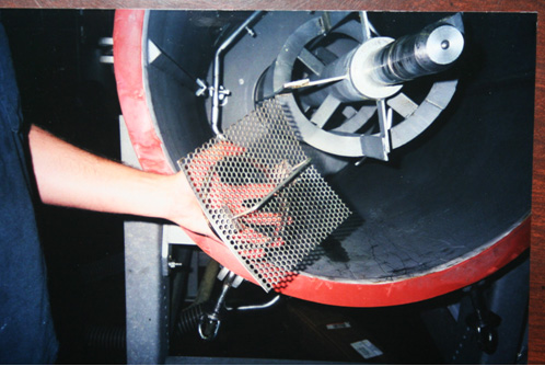
REMOVING AND RE-INSTALLING THE FABRIC SLEEVE ASSEMBLY
To remove the assembly that holds the fabric sleeves, first shut off the flow into the Fiber Filter and then lock out the machine. It will help to operate the backflush system before disassembly. Set the level of the rotor at an attitude, most generally the horizontal position, which will be convenient for removing the discharge head and sleeve assembly.
An Allen head wrench is used to loosen the setscrews (usually four) that hold the inner race of the bearing that is mounted to the discharge head.
At this point, there are two options: (1) The springs can be left in place and the entire discharge head and sleeve assembly can be removed as one piece, or (2) the springs can be removed, followed by the discharge head. Once this is done, the sleeve assembly can be slipped out of the barrel of the Fiber Filter.
Note that the discharge bearing comes off with the head; there is no need to loosen the four bolts which hold the bearing.
Axial rails support the sleeve assembly. The inlet end slides over a spout ring in the inlet head of the machine.
Look through the open end of the sleeve assembly to make sure the fabric is not dragged or pushed into the rotor. Do this during both disassembly and re-assembly operations.
Following re-assembly and tightening the springs of the Fiber Filter, check the fabric sleeves through the inspection panels. This should be done before putting power to the machine, as a loose sleeve will become entangled in the rotor.
ROTOR CONFIGURATION
Several rotor designs are available for Vincent Fiber Filters. Most designs have straight paddles with ribbon flighting added to direct fiber toward the discharge. Contrary to normal screw conveyor logic, a tight pitch ribbon flight is used to move large quantities of solids, while a long pitch ribbon flight is used when the solids flow is minimal. Switching to a long pitch rotor can reduce excessive water being present in the discharge sludge.
ROTOR INSTALLATION
The rotor is supported by two spherical self-aligning roller bearings. These are mounted at the drive end and on the discharge head.
Special care must be taken when re-installing a rotor. The drive end of the rotor must be slipped through the shaft seal housing. To do this properly, remove the seal housing and insert the end of the rotor through the hole in the inlet head. The rotor should be pushed in just far enough that the seal housing can be slipped onto the end of the shaft. Then the rotor shaft can be pushed through the drive-end bearing until the thrust shoulder on the rotor shaft seats against the bearing. The seals can be damaged if the seal housing is not loosened during rotor installation.
Care must be taken that the rotor spins freely after assembly. Rarely, this may require relocating one or both of the two main bearings. Both of these bearings are self-aligning. The rotor shaft should not ride heavily on the seal housing when assembly and alignment are complete.
SHAFT SEALS
Fiber Filters use Johns Manville JM Clipper lip seals. These are the c-cup style. There will be a pair in the housing at the drive (inlet) end of the machine, mounted on the inlet head. These seals have internal springs to hold the lip against the shaft.
BACKFLUSH SYSTEM
Most Fiber Filters are supplied with a backflush system. This consists of a pressure boosting pump, a solenoid valve to open the water line when the pump is in operation, a filter for filtering the flush water, and a control panel. The control panel has a timer with two clocks: the top clock sets the time interval between flushings, and the lower clock sets the time duration that the pump will run during the flush cycle. There is also a solenoid valve which supplies air to the air cylinder which is used to move the spray ring assembly along the length of the sleeves.
REPLACEMENT PARTS
The most common wear parts in the Fiber Filter are the sleeves, the sleeve clamps, the seals, and the bearings. These are stocked by Vincent. Be sure to specify the Serial Number of your machine when ordering replacement parts. The seals and bearings, like the sheaves and belts, are standard OEM components that can be purchased from the original equipment manufacturer (OEM). The specification of these items is included in the O&M Manual.
SAFETY
These Operating Hints have left unstated the obvious safety hazard: a Fiber Filter, like any rotating machine, is unforgiving. If clothing or limb gets caught in the rotor it will not stop until damage has been done.
The easiest way to get hurt with a Fiber Filter is to reach inside the sludge discharge while the machine is operating. There has already been one minor injury as a result of this, so do no let yourself become the second.
A second way to get hurt is to press your hand or finger against the fabric sleeve while the rotor is in operation. If you push your finger through a hole, the rotor will cut off the finger.
The use of common sense is all that is required.
Robert Johnston, P.E.